2 wire sensor is basically a loop-powered device without requiring a separate supply voltage (the source voltage is supplied to the destination device) whereas the 3 wire sensor is a self-powered device meaning, you supply source voltage to the sensor and it can drive a 4-20 ma input device directly without the destination device requiring any s
Sensor Circuit Board: Over 1,066 Royalty-Free Licensable Stock Illustrations & Drawings | Shutterstock
The 2wire proximity sensor wiring diagram is typically used to show how two components, such as the proximity sensor and the controller, interact with each other. The diagram will provide an in-depth view of the connection between the two devices, including which wires should be connected and which must be isolated.

Source Image: pinterest.com
Download Image
Two wire proximity sensor connection with relay 220vac is shown in this video. AC 2 wire proximity switch is widely used in factory automation and in many ma

Source Image: pinterest.com
Download Image
2 wire proximity sensor wiring connection diagram | two wire sensor | Ali Technical Power – YouTube A 2wire proximity sensor is one of the most commonly used types, known for its simplicity and cost-effectiveness. This guide will walk you through the step-by-step process of wiring a 2-wire proximity sensor to a PLC, ensuring proper functionality and reliable detection. Step 1: Choose the Right Proximity Sensor
Source Image: topens.com
Download Image
2 Wire Proximity Sensor Wiring Diagram
A 2wire proximity sensor is one of the most commonly used types, known for its simplicity and cost-effectiveness. This guide will walk you through the step-by-step process of wiring a 2-wire proximity sensor to a PLC, ensuring proper functionality and reliable detection. Step 1: Choose the Right Proximity Sensor In the wiring diagrams below you will notice the different call outs for the Polarized vs. Non-Polarized offerings. Note: (-) Indication of Non-Polarized wiring. While 3-wire sensors are a more common option as they offer very low leakage current, 2 wire offerings do have their advantages per application. They can be wired in a sinking (NPN) or
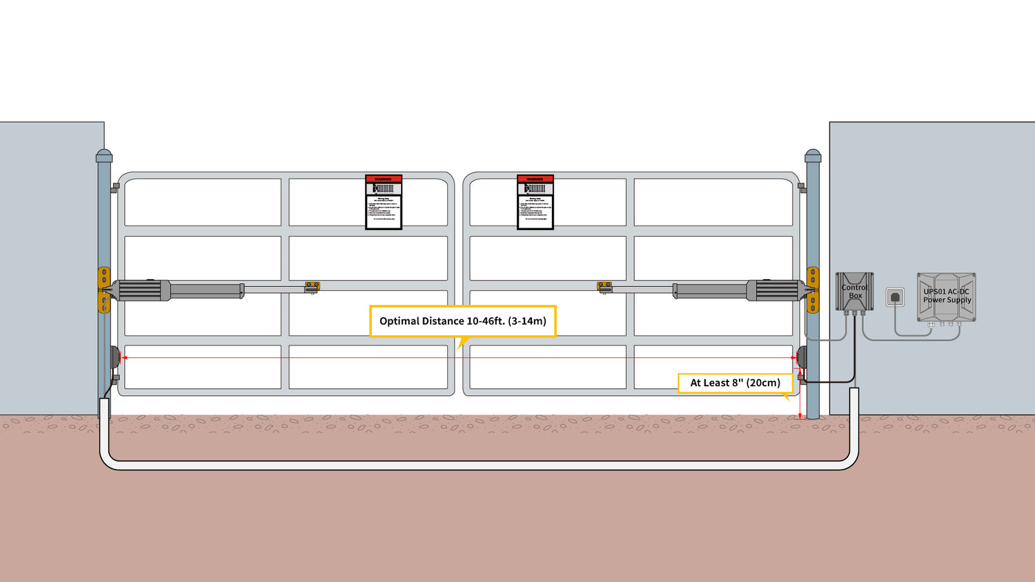
How to Install TOPENS TC102 Photocell Beam Sensor
How to use Limit Switch | Limit Switch Connection | Limit Switch Connection With Motor Welcome to Electro Engage! 🚀 In this comprehensive video, we dive deep into the 2 Wire Proximity Analog Inductive Proximity Sensor [Working Principle, Features, Applications] – Dubai Sensor
![Analog Inductive Proximity Sensor [Working Principle, Features, Applications] - Dubai Sensor](https://cdn11.bigcommerce.com/s-sgprcd6/images/stencil/1193x795/uploaded_images/analog-inductive-proximity-sensor.jpg?t=1645344232)
Source Image: dubai-sensor.com
Download Image
Proximity switches Circuit Diagram Operation Instrumentation Tools | Proximity switch, Circuit diagram, Circuit How to use Limit Switch | Limit Switch Connection | Limit Switch Connection With Motor Welcome to Electro Engage! 🚀 In this comprehensive video, we dive deep into the 2 Wire Proximity

Source Image: pinterest.com
Download Image
Sensor Circuit Board: Over 1,066 Royalty-Free Licensable Stock Illustrations & Drawings | Shutterstock 2 wire sensor is basically a loop-powered device without requiring a separate supply voltage (the source voltage is supplied to the destination device) whereas the 3 wire sensor is a self-powered device meaning, you supply source voltage to the sensor and it can drive a 4-20 ma input device directly without the destination device requiring any s

Source Image: shutterstock.com
Download Image
2 wire proximity sensor wiring connection diagram | two wire sensor | Ali Technical Power – YouTube Two wire proximity sensor connection with relay 220vac is shown in this video. AC 2 wire proximity switch is widely used in factory automation and in many ma

Source Image: youtube.com
Download Image
2 wire proximity sensor wiring diagram||proximity sensor||2wire proximity sensor wiring kaise karen – YouTube Jan 15, 2024Proximity sensors can be classified into two main types based on their output configuration: NPN (normally open) and PNP (normally closed). These classifications refer to the type of transistor used in the sensor’s output circuitry. Here’s a brief overview of each type:

Source Image: youtube.com
Download Image
How To Make 2 Wire Sensor in Magnetic Contactor Connection Diagram | proximity sensor – YouTube A 2wire proximity sensor is one of the most commonly used types, known for its simplicity and cost-effectiveness. This guide will walk you through the step-by-step process of wiring a 2-wire proximity sensor to a PLC, ensuring proper functionality and reliable detection. Step 1: Choose the Right Proximity Sensor

Source Image: youtube.com
Download Image
Datexel Signal Converter Dual RTD Input, Analog Output – DAT2166 In the wiring diagrams below you will notice the different call outs for the Polarized vs. Non-Polarized offerings. Note: (-) Indication of Non-Polarized wiring. While 3-wire sensors are a more common option as they offer very low leakage current, 2 wire offerings do have their advantages per application. They can be wired in a sinking (NPN) or

Source Image: dubai-sensor.com
Download Image
Proximity switches Circuit Diagram Operation Instrumentation Tools | Proximity switch, Circuit diagram, Circuit
Datexel Signal Converter Dual RTD Input, Analog Output – DAT2166 The 2wire proximity sensor wiring diagram is typically used to show how two components, such as the proximity sensor and the controller, interact with each other. The diagram will provide an in-depth view of the connection between the two devices, including which wires should be connected and which must be isolated.
2 wire proximity sensor wiring connection diagram | two wire sensor | Ali Technical Power – YouTube How To Make 2 Wire Sensor in Magnetic Contactor Connection Diagram | proximity sensor – YouTube Jan 15, 2024Proximity sensors can be classified into two main types based on their output configuration: NPN (normally open) and PNP (normally closed). These classifications refer to the type of transistor used in the sensor’s output circuitry. Here’s a brief overview of each type:

